

.svg?la=en&revision=cee9767f-8e72-4d76-a07a-14ba25688269&hash=ADF64722447408F8CA70B4436F59CB64)

Vertical Planar Near-Field Systems - Medium
Model: PNF-XYV
Features
- 1.8 m x 1.8 m (6 ft x 6 ft) to 6.1 m x 6.1 m (20 ft x 20 ft) scan area
- Precision rack and pinion drive system
- Inverted “T” frame design for high accuracy and repeatability
- Exceptional planarity with active structure correction
- UHF to mm-Wave measurements
- Suitable for far-field antenna patterns, array calibration, and holographic back projection
- CNF, SNF, and direct illumination far-field options available
- System-level testing (EIRP, G/T, SFD, group delay, gain-frequency response) available with Active Antenna Test Suite (SYS-AATS) upgrade option
Description
NSI-MI’s Vertical Planar Near-Field (PNF-XYV) systems are ideally suited for testing the forward hemisphere of medium and high gain antennas with gain greater than around 15 dBi. PNF-XYV systems are the perfect solution to accurately and efficiently characterize reflectors, phased arrays, large aperture, or satellite antennas, with angular coverage up to ≤±80° from boresight. The medium-size family of VPNF systems offers scan plane sizes ranging from 1.8 m x 1.8 m (6 ft x 6 ft) to 6.1 m x 6.1 m (20 ft x 20 ft). Each system comes equipped with high-capacity probe polarization and Z-translation stages, supporting probes operational down to 0.75 GHz.
Constructed of durable steel and featuring an inverted "T" design, our medium-size VPNF systems offer superior stability and accuracy. The welded cross-braced dual-rail base ensures high stability, while the robust design makes maintenance and alignment a breeze. The integrated Z-axis is used for automatic planarity correction, ensuring maximum system precision and reliability.
Smaller and larger scan plane sizes are available as part of the small and large-size PNF-XYV product lines, respectively. These systems can be augmented with Cylindrical Near-Field (CNF), Spherical Near-Field (SNF), or Far- Field (FF) positioners to greatly increase the angular coverage and reduce the supported low frequency, for enhanced versatility.
Planar Near-Field Models
PNF-XYV-1.8x1.8

PNF-XYV-2.4x2.4
PNF-XYV-3.6x3.6
PNF-XYV-4.6x4.6
PNF-XYV-5.5x5.5
PNF-XYV-6.1x6.1
Finding the right size for your application
PNF scanners are ideally suited for characterizing the forward hemisphere of directional antennas. The scan plane required for your application will depend on:
- D - The maximum diameter of the antenna under test (AUT).
- Z – The probe-to-AUT separation, 3 - 5λ recommended.
- Ø – Maximum desired far-field angular coverage (± deg).
- P – Diameter of the near-field probe’s aperture.
The diagram shows a side view of an AUT with all critical dimensions identified. To calculate the Y-axis span required for accurate PNF characterization, the equation below is used. This should be repeated to calculate the X-axis span.
Equation: L= D + P + 2Z Tan(Ø)

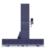
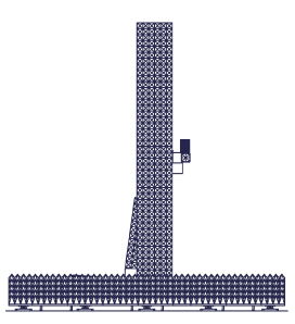
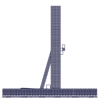
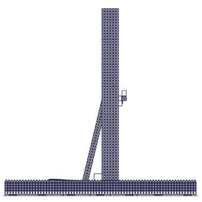
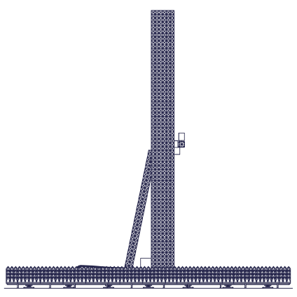
Scanner Construction
The major elements of the PNF-XYV are highlighted below.

Physical Parameters

-
Specifications
-
Applications
-
Absorber Kits
-
Standard Features
-
Available Add-Ons
| Parameters | PNF-XYV-1.8x1.8 | PNF-XYV-2.4x2.4 | PNF-XYV-3.6x3.6 | PNF-XYV-4.6x4.6 | PNF-XYV-5.5x5.5 | PNF-XYV-6.1x6.1 |
| Pre-configured model | ✔ | ✔ | ✔ | ✔ | ✔ | ✖ |
| Construction | Inverted “T” frame, steel construction | |||||
| Drive system | Rack & pinion with stepper motors | |||||
| X-Y absorber kit | 20 cm (8”) pyramidal | 30 cm (12”) pyramidal | ||||
| Absorber power handling | <1 KW/m2 (0.65 W/in2); (higher power handling options available) |
|||||
| Scan area | 1.83 x 1.83 m (6 x 6 ft) |
2.44 x 2.44 m (8 x 8 ft) |
3.66 x 3.66 m (12 x 12 ft) |
4.57 x 4.57 m (15 x 15 ft) |
5.49 x 5.49 m (18 x 18 ft) |
6.10 x 6.10 m (20 x 20 ft) |
| Z access travel | 300 mm (12 in.) | |||||
| Corrected planarity (RMS) | < 0.05 mm (0.002 in.) | |||||
| Resolution (X, Y) | < 0.025 mm (0.001 in.) | |||||
| Position repeatability (X, Y) RMS | < 0.05 mm (0.002 in.) | |||||
| Scan speed | X: 0.25 m/s (10 in./s) Y: 0.38 m/s (15 in./s) |
|||||
| Max probe weight | 19 kg (42 lb) | |||||
| Frequency range | 0.75 – 170 GHz; (lower frequency options available for SNF/FF add-ons) |
|||||
| Supported Equipment, Software, and Accessories | ||||||
| Position controllers | ELE-PAC Precision Axis Controller ELE-IMC Intelligent Measurement Controller ELE-PMC Precision Motion Controller |
|||||
| Supported software | SW-A4 Advanced Antenna Acquisition and Analysis (A4) NSI2000 Remote control via SCPI command set (ELE-PAC & ELE-PMC only) |
|||||
| RF receivers | ELE-VFA Vector Field Analyzer™ Select Keysight VNA models Select Rohde & Schwarz VNA models |
|||||
| Frequency extension | Select Virginia Diodes Inc. (VDI) frequency extension modules | |||||
| AUT alignment | Precision Laser Alignment Sensor | |||||
| Probe antennas | ANT-WGP Open-Ended Waveguide Probes ANT-DPP Dual Polarized Probes (select models) ANT-BRP Broadband Ridged Probes* ANT-QRH Quad Ridged Horn Antennas* |
|||||
*Only suitable for SNF/FF add-on options.
| Physical Parameters | PNF-XYV-1.8x1.8 | PNF-XYV-2.4x2.4 | PNF-XYV-3.6x3.6 | PNF-XYV-4.6x4.6 | PNF-XYV-5.5x5.5 | PNF-XYV-6.1x6.1 |
| Overall width | 3.14 m (124 in.) |
3.67 m (145 in.) |
4.92 m (194 in.) |
6.25 m (246 in.) |
7.15 m (282 in.) |
7.77 m (306 in.) |
| Depth (Z-axis extended) | 1.79 m (71 in.) |
1.79 m (71 in.) |
1.79 m (71 in.) |
2.40 m (95 in.) |
2.40 m (95 in.) |
2.40 m (95 in.) |
| Overall height | 3.10 m (123 in.) |
3.71 m (147 in.) |
4.97 m (196 in.) |
5.92 m (233 in.) |
6.86 m (270 in.) |
7.47 m (294 in.) |
| Scan center height | 1.71 m (68 in.) |
2.02 m (80 in.) |
2.64 m (105 in.) |
3.10 m (123 in.) |
3.56 m (141 in.) |
3.87 m (153 in.) |
| W1 | 0.94 m (38 in.) |
1.25 m (50 in.) |
1.86 m (74 in.) |
2.30 m (91 in.) |
2.77 m (110 in.) |
3.07 m (121 in.) |
| W2 | 2.19 m (87 in.) |
2.43 m (96 in.) |
3.06 m (121 in.) |
3.94 m (156 in.) |
4.38 m (173 in.) |
4.71 m (186 in.) |
| Weight | 1,184 kg (2,611 lb) |
1,409 kg (3,107 lb) |
1,849 kg (4,076 lb) |
2,624 kg (5,785 lb) |
2,981 kg (6,572 lb) |
3,167 kg (6,981 lb) |
| Floor interface | Leveling feet | Fixators in grout | ||||
| Environmental Parameters | ||||||
| Operating conditions | Indoor | |||||
| Operating temperature range | 10 to 40 °C (50 to 104 °F) | |||||
| Operating relative humidity | 35 – 75 % Non-Condensing | |||||
| Measurement temperature variation | ±1.2 °C (± 2 °F) | |||||
- General Antenna Testing
- Satellite Antenna Testing
- Wireless
- Phased array antenna testing and calibration
- Production and R&D environments
Scanner Absorber Kits
Several scanner absorber kits are available for the PNF-XYV product line. The standard option includes polyurethane absorber, which supports RF power levels of ≤ 1 kW/m2 at full continuous wave (CW) power. Some antennas with active amplification operating in transmit mode might exceed this limit when tested at CW power. For these cases, one can choose to characterize the AUT in pulsed mode to ensure that power levels at the scanner are within the safe limit or upgrade the absorber kit. NSI-MI offers several upgrade options to increase the power handling to 10 kW/m2 and beyond. Contact NSI-MI to help you determine which absorber kit is right for your application.

Foam Absorber
Standard option
≤ 1 kW/m2

Filter Foam Absorber
High-power option
≤ ~4 kW/m2

Honeycomb Absorber
Very high-power option
≤ ~10 kW/m2


Honeycomb Absorber with Forced Air Cooling - Extremely high-power option (air flow dependent)

Probe Polarization Rotator
The PNF-XYV series includes a MEC-POL-0.1 polarization positioner. This axis enables rotation of the probe antenna on the planar near-field system. The pol-stage is a high accuracy rotational positioner driven by a precision stepper motor. It has an integral RF rotary joint, selected based on the required frequency range of operation. The integrated limit switches can be bypassed in software to enable continuous rotation over 360°. This positioner is used to mount all probes for PNF testing, but its rotation capabilities are not required when dual-polarized probes are installed.

Probe Translation Stage
NSI-MI will provide a MEC-Z-0.3 heavy duty linear translation stage. The high accuracy probe translation stage is used for minor adjustments of the probe’s position to improve the scanner’s native planarity to < 0.05 mm RMS over the entire scan plane. This translation stage can also be used to adjust the spacing between the probe and AUT with over 300 mm of total travel available.

Planar Near-Field Structure Correction
NSI-MI enhances PNF-XYV system accuracy through active structure correction. During installation, an optical survey of scanner flatness generates a lookup table, uploaded to the system controller for automatic error correction after installation or calibration. Flatness should be re-measured, and the table updated if the scanner is relocated or after seismic events. The computer-controlled Z-axis dynamically adjusts the probe position during measurement, ensuring broad angular coverage. This process often improves planarity by an order of magnitude. Every PNF-XYV system includes this feature.


Cylindrical Near-Field Add-Ons
Support for CNF measurements is made available with our line of CNF-ADD add-on packages. Each upgrade kit includes an AUT positioner and our CNF acquisition and processing software. All necessary RF, motor, and control cabling, program management and engineering services are also included. CNF measurements expand angular coverage in Azimuth to ±180°, making it perfect for fan beam antennas and to analyze wide side or back lobes within that plane. This upgrade is also useful for counter-steering phased array antennas whose main beam is scanned near broadside along Azimuth.
Some examples of CNF upgrades available for the PNF-XYV product line are highlighted below:

| Parameters | CNF-ADD-AZ-0.5 | CNF-ADD-AZ-20 | CNF-ADD-AZ-45 |
| Max AUT weight | 1,996 kg (4,400 lb) | 4,536 kg (10,000 lb) | 9,072 kg (20,000 lb) |
| Bending Moment, Operation | 477 Nm (352 ft-lb) | 13,558 Nm (10,000 ft-lb) | 30,506 Nm (22,500 ft-lb) |
| Maximum Speed | 3.3 RPM | 5 RPM | 1.5 RPM |
| Azimuth rotator model | MEC-AZ-0.5 | MEC-AZ-20 | MEC-AZ-45 |
Spherical Near-Field Add-Ons
Support for SNF measurements is made possible through our line of SNF-ADD add-on packages. Each upgrade kit includes an AUT positioner, configured as a Phi-over-Theta stack-up, to enable full sphere measurements. SNF acquisition and processing software is also included, along with all necessary RF, motor, and control cabling, program management and engineering services necessary to deliver and install the upgrade. These add-on packages greatly increase the flexibility of the PNF-XYV system. Directional antennas can be efficiently characterized in PNF mode, while high gain or low frequency antennas will benefit from the SNF geometry for full sphere characterization. Pairing the SNF-ADD upgrade with a floor slide further increases flexibility.
Some examples of SNF upgrades available for the PNF-XYV product line are highlighted below:

| Parameters | SNF-ADD-0.7 | SNF-ADD-1.3 | SNF-ADD-2.0 | SNF-ADD-3.0 |
| Max AUT weight | 18 kg (40 lb) | 75 kg (165 lb) | 136 kg (300 lb) | 454 kg (1,000 lb) |
| Max bending moment | 41 Nm (30 ft-lb) | 168 Nm (124 ft-lb) | 305 Nm (225 ft-lb) | 1,016 Nm (750 ft-lb) |
| Max AUT diameter | 0.7 m (30 in.) | 1.3 m (51 in.) | 2.0 m (79 in.) | 3.0 m (118 in.) |
| Max speed (theta-axis) | 1.7 RPM | 1.7 RPM | 3.3 RPM | 1.0 RPM |
| Max speed (phi-axis) | 1.7 RPM | 1.7 RPM | 3.3 RPM | 1.0 RPM |
| Theta-axis rotator model | MEC-POL-0.1 | MEC-POL-0.5 | MEC-POL-0.5 | MEC-POL-20 |
| Phi-axis rotator model | MEC-AZ-0.5 | MEC-AZ-0.5 | MEC-AZ-20 | MEC-AZ-20 |
Floor Slide Add-Ons
Floor slides (MEC-FS) can be added to your system for increased flexibility. These positioners are often added to PNF-XYV systems to facilitate AUT installation or to change probe-to-AUT spacing for multi-purpose ranges. Floor slides can be customized to any length, with standard options available from 0.9 m (3 ft) to 7.5 m (25 ft). Manual and motorized options are available and are compatible with the CNF-ADD and SNF-ADD packages.


Precision Laser Alignment System
When accurate mechanical-to-electrical boresight data is required, NSI-MI recommends our Precision Laser Alignment System. This solution uses a non-contact laser displacement sensor to measure the distance between the near-field scan plane and three or more reference points on your AUT or mounting frame. The alignment system, along with the accompanying software tools and graphical user interface, can record X, Y and Z coordinates of reference point positions on the AUT with <0.001 mm resolution. This allows for quick and easy calculation of AUT misalignment of Azimuth, Elevation, and Roll.


