

.svg?la=en&revision=cee9767f-8e72-4d76-a07a-14ba25688269&hash=ADF64722447408F8CA70B4436F59CB64)

Vertical Planar Near-Field Systems - Large
Model: PNF-XYV
Features
- 9.1 m x 9.1 m (30 ft x 30 ft) to 32.9 m x 15.2 m (108 ft x 50 ft) scan area, "custom sizes available"
- Inverted “T” frame design for high accuracy and repeatability
- Exceptional planarity with active structure correction
- UHF to mm-Wave measurements
- Suitable for far-field antenna patterns, array calibration, and holographic back projection
- CNF, SNF, and direct illumination far-field options available
- System-level testing (EIRP, G/T, SFD, group delay, gain-frequency response) available with Active Antenna Test Suite (SYS-AATS) upgrade option
Description
NSI-MI’s Vertical Planar Near-Field (PNF-XYV) systems are ideally suited for testing the forward hemisphere of medium and high gain antennas with gain greater than around 15 dBi. PNF-XYV systems are the perfect solution to accurately and efficiently characterize reflectors, phased arrays, large aperture, or satellite antennas, with angular coverage up to ≤±80° from boresight. The large-size family of PNF systems offers scan plane sizes ranging from 9.1 m x 9.1 m (30 ft x 30 ft) to 32.9 m x 15.2 m (108 ft x 50 ft). Some standard sizes are shown herein, but custom sizes are routinely delivered to optimize facility size for your application. Each system comes equipped with high-capacity probe polarization and Z-translation stages, supporting probes operational down to 0.5 GHz.
Constructed of durable steel, our large-size VPNF systems offer superior stability and accuracy. The welded cross-braced dual-rail base ensures high stability, while the robust design makes maintenance and alignment a breeze. The integrated Z-axis is used for automatic planarity correction, ensuring maximum system precision and reliability.
Smaller and medium scan plane sizes are available as part of the small and medium-size PNF-XYV product lines, respectively. These systems can be augmented with Cylindrical Near-Field (CNF), Spherical Near-Field (SNF), or Far-Field (FF) positioners to greatly increase the angular coverage and reduce the supported low frequency, for enhanced versatility.
Customer Spotlight - NSTF & STFC RAL Space
In this edition of our Customer Spotlight, discover how NSTF and STFC RAL Space partnered with NSI-MI Technologies to validate next-gen satellite communications using our advanced vertical planar near-field scanner and a custom-built anechoic chamber.
Read more
Finding the right size for your application
PNF scanners are ideally suited for characterizing the forward hemisphere of directional antennas. The scan plane required for your application will depend on:
- D - The maximum diameter of the antenna under test (AUT).
- Z – The probe-to-AUT separation, 3 - 5λ recommended.
- Ø – Maximum desired far-field angular coverage (± deg).
- P – Diameter of the near-field probe’s aperture.
The diagram shows a side view of an AUT with all critical dimensions identified. To calculate the Y-axis span required for accurate PNF characterization, the equation below is used. This should be repeated to calculate the X-axis span.
Equation: L= D + P + 2Z Tan(Ø)

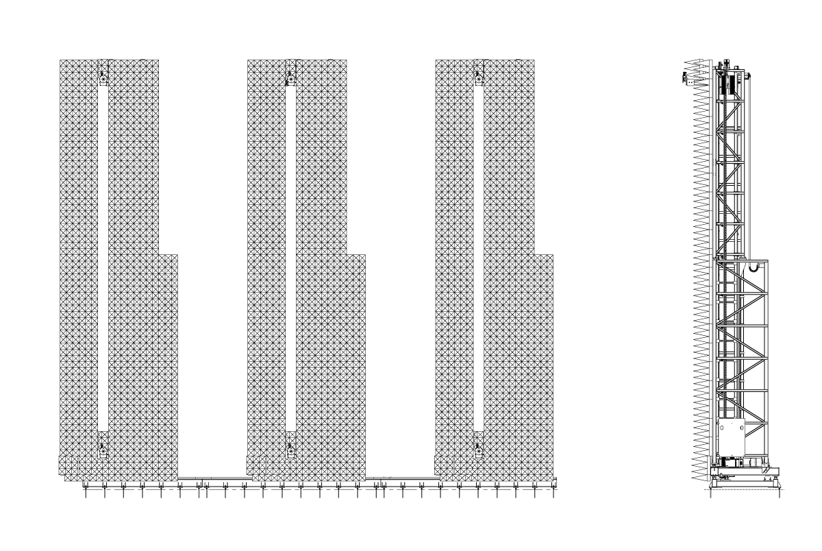
Scanner Construction
The major elements of the PNF-XYV are highlighted below.

Physical Parameters

-
Specifications
-
Applications
-
Absorber Kits
-
Standard Features
-
Available Add-Ons
| Parameters | PNF-XYV-9.1x9.1 | PNF-XYV-12.2x12.2 | PNF-XYV-18.2x12.2 | PNF-XYV-32.9x15.2 |
| Construction | Inverted “T” frame, steel construction | |||
| Drive system | Y-axis: rack and pinion with precision servo motor X-axis: friction drive with precision servo motor |
|||
| X-Y absorber kit | 61 cm (24 in.) flex-rated pyramidal | |||
| Absorber power handling | <1 KW/m2 (0.65 W/in2); (higher power handling options available) |
|||
| Scan area | 9.1 x 9.1 m (30 x 30 ft) |
12.2 x 12.2 m (40 x 40 ft) |
18.2 x 12.2 m (60 x 40 ft) |
32.9 x 15.2 m (108 x 50 ft) |
| Z access travel | 300 mm (12 in.) | |||
| Corrected planarity (RMS) | < 0.10 mm (0.004 in.) | <0.13 mm (0.005 in.) | ||
| Resolution (X, Y) | <0.025 mm (0.001 in.) | |||
| Position repeatability (X, Y) RMS | < 0.05 mm (0.002 in.) | |||
| Scan speed | X: 0.25 m/s (10 in./s) Y: 0.50 m/s (20 in./s) |
|||
| Max probe weight | 91 kg (200 lb) | |||
| Frequency range | 0.5 – 170 GHz; (lower frequency options available for SNF/FF add-ons) |
|||
| Supported Equipment, Software, and Accessories | ||||
| Position controllers | ELE-PAC Precision Axis Controller ELE-IMC Intelligent Measurement Controller ELE-PMC Precision Motion Controller |
|||
| Supported software | SW-A4 Advanced Antenna Acquisition and Analysis (A4) NSI2000 Remote control via SCPI command set (ELE-PAC & ELE-PMC only) |
|||
| RF receivers | ELE-VFA Vector Field Analyzer™ Select Keysight VNA models Select Rohde & Schwarz VNA models |
|||
| Frequency extension | Select Virginia Diodes Inc. (VDI) frequency extension modules | |||
| AUT alignment | Precision Laser Alignment Sensor | |||
| Probe antennas | ANT-WGP Open-Ended Waveguide Probes ANT-DPP Dual Polarized Probes (select models) ANT-BRP Broadband Ridged Probes* ANT-QRH Quad Ridged Horn Antennas* |
|||
*Only suitable for SNF/FF add-on options.
Physical and Environmental Specifications
| Physical Parameters | PNF-XYV-9.1x9.1 | PNF-XYV-12.2x12.2 | PNF-XYV-18.2x12.2 | PNF-XYV-32.9x15.2 |
| Overall width | 11.43 m (450 in.) | 14.91 m (587 in.) | 21.01 m (827 in.) | 36.73 m (1,446 in.) |
| Depth (Z-axis extended) | 2.69 m (106 in.) | 3.15 m (124 in.) | 3.15 m (124 in.) | 4.27 m (168 in.) |
| Overall height | 11.10 m (437 in.) | 14.12 m (556 in.) | 14.12 m (556 in.) | 17.98 m (708 in.) |
| Scan center height | 5.79 m (228 in.) | 7.32 m (288 in.) | 7.32 m (288 in.) | 9.55 m (376 in.) |
| W1 | 6.86 m (106 in.) | 8.81 m (347 in.) | 11.86 m (467 in.) | 20.27 m (798 in.) |
| W2 | 2.74 m (1086 in.) | 6.09 m (240 in.) | 9.14 m (360 in.) | 16.46 m (648 in.) |
| Weight | 8,656 kg (19,083 lb) | 12,655 kg (27,900 lb) | 14,515 kg (32,002 lb) | 32,103 kg (70,776 lb) |
| Floor interface | Anchors in epoxy | |||
| Environmental Parameters | ||||
| Operating conditions | Indoor | |||
| Operating temperature range | 10 to 40 °C (50 to 104 °F) | |||
| Operating relative humidity | 35 – 75 % Non-condensing | |||
| Storage relative humidity | 35 – 75 % Non-Condensing | |||
| Measurement temperature variation | ±1.2 °C (± 2 °F) | |||
- General Antenna Testing
- Satellite Antenna Testing
- Wireless
- Phased array antenna testing and calibration
- Production and R&D environments
Scanner Absorber Kits
Several scanner absorber kits are available for the PNF-XYV product line. The standard option includes polyurethane absorber, which supports RF power levels of ≤ 1 kW/m2 at full continuous wave (CW) power. Some antennas with active amplification operating in transmit mode might exceed this limit when tested at CW power. For these cases, one can choose to characterize the AUT in pulsed mode to ensure that power levels at the scanner are within the safe limit or upgrade the absorber kit. NSI-MI offers several upgrade options to increase the power handling to 10 kW/m2 and beyond. Contact NSI-MI to help you determine which absorber kit is right for your application.

Foam Absorber
Standard option
≤ 1 kW/m2

Filter Foam Absorber
High-power option
≤ ~4 kW/m2

Honeycomb Absorber
Very high-power option
≤ ~10 kW/m2


Honeycomb Absorber with Forced Air Cooling - Extremely high-power option (air flow dependent)

Heavy-Duty Probe Polarization Rotator
The PNF-XYV series includes a heavy-duty polarization positioner. This axis enables rotation of the probe antenna on the planar near-field system. The pol-stage is a high accuracy rotational positioner driven by a precision servo motor. It has an integral RF rotary joint, selected based on the required frequency range of operation. This positioner is used to mount all probes for PNF testing, but its rotation capabilities are not required when dual-polarized probes are installed.

Probe Translation Stage
NSI-MI will provide a MEC-Z-0.3 heavy duty linear translation stage. The high accuracy probe translation stage is used for minor adjustments of the probe’s position to improve the scanner’s native planarity to < 0.05 mm RMS over the entire scan plane. This translation stage can also be used to adjust the spacing between the probe and AUT with over 300 mm of total travel available.

Planar Near-Field Structure Correction
NSI-MI enhances PNF-XYV system accuracy through active structure correction. During installation, an optical survey of scanner flatness generates a lookup table, uploaded to the system controller for automatic error correction after installation or calibration. Flatness should be re-measured, and the table updated if the scanner is relocated or after seismic events. The computer-controlled Z-axis dynamically adjusts the probe position during measurement, ensuring broad angular coverage. This process often improves planarity by an order of magnitude. Every PNF-XYV system includes this feature.


Custom AUT Positioner
Many applications require a positioner stack-up installed in front of the PNF scanner to mount and/or move the AUT along one or more axes. For the large PNF-XYV series, NSI-MI will work with you to select a custom positioner stack-up that meets your needs. This positioner can be used to facilitate AUT alignment, to center the test article, to simplify AUT loading, or to enable additional acquisition modes (spherical near-field [SNF], cylindrical near-field [CNF], or far-field [FF]). Directional antennas can be efficiently characterized in PNF mode, while high gain or low frequency antennas will benefit from SNF, CNF or FF acquisition modes, greatly increasing flexibility. Every upgrade kit includes the appropriate acquisition and processing software, all necessary RF, motor, and control cabling, program management and engineering services necessary to deliver and install the upgrade. Contact NSI-MI to help you determine which AUT stack-up is right for your application.

Dual Absorber Wing
For some applications, NSI-MI recommends installing dual-absorber wings to PNF-XYV scanners. This is particularly important for phased arrays or satellite applications where the main beam is steered far off boresight. The additional absorber coverage minimizes RF reflections for these challenging measurement scenarios. Note: that this option adds approx. 1.4 m (4.5 ft.) to the overall width of the scanner. NSI-MI's team of experts can help you decide if this option is right for your application.
Precision Laser Alignment System
When accurate mechanical-to-electrical boresight data is required, NSI-MI recommends our Precision Laser Alignment System. This solution uses a non-contact laser displacement sensor to measure the distance between the near-field scan plane and three or more reference points on your AUT or mounting frame. The alignment system, along with the accompanying software tools and graphical user interface, can record X, Y and Z coordinates of reference point positions on the AUT with <0.001 mm resolution. This allows for quick and easy calculation of AUT misalignment of Azimuth, Elevation, and Roll.


