.svg?la=en&revision=cee9767f-8e72-4d76-a07a-14ba25688269&hash=ADF64722447408F8CA70B4436F59CB64)

Large Compact Range Systems
Model: CRS-CRC / CRS-CSC / CRS-ESC
Features
- Versatile Quiet Zone Sizes
- Broad Frequency Coverage
- Superior Quiet Zone Performance
- Robust Payload Capacity
- Precision Engineering
- Multi-Application Capability
- Flexible System Enhancements
Description
NSI-MI’s Large Compact Range Systems (CRS-CRC / CRS-CSC / CRS-ESC) deliver exceptional performance for testing directive antennas—offering a smarter alternative to traditional far-field and near-field ranges. Designed for indoor use, these systems require significantly less space than far-field ranges while maintaining, or even exceeding, their performance. This indoor capability also ensures greater test availability, free from weather-related delays or logistical constraints.
Unlike near-field systems, compact ranges streamline the testing process by eliminating the need to scan the entire antenna aperture to obtain a single far-field pattern cut. This results in faster, more efficient evaluations of antenna performance.
Compact Range System Models

CRS-CSC-3.7-1
CRS-ESC-2.4x3.7-0.5
CRS-CRC-5-0.35
CRS-CSC-6-0.5
CRS-ESC-5.5x9.1-0.5
CRS-ESC-7.3x10.7-0.5
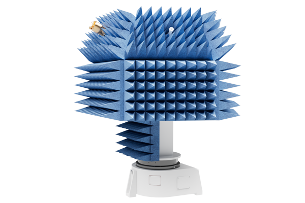
Precision Reflector Technology: Creating the Ideal Quiet Zone for Antenna Testing
At the heart of the compact range is a precision-engineered reflector system. It generates a planar electromagnetic wavefront by collimating spherical waves from a feed antenna positioned at the reflector’s focal point. This creates a “quiet zone” where the antenna under test (AUT) is exposed to a highly uniform field, ideal for accurate measurements. The reflector’s prime focus virtual vertex design minimizes multipath interference by positioning the vertex below the reflector surface, keeping the feed antenna clear of the test zone’s collimated energy.
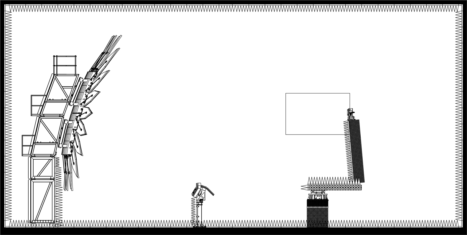
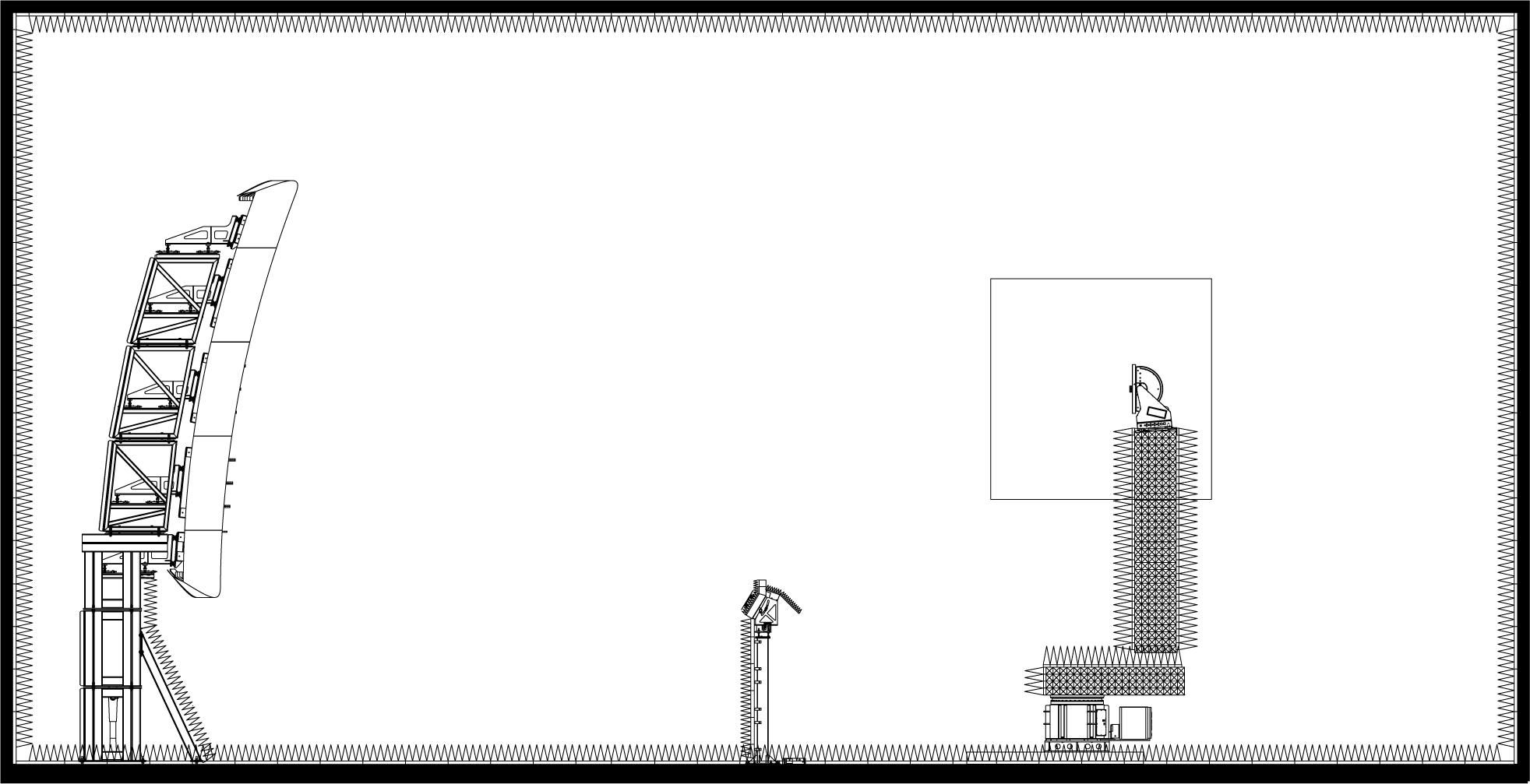
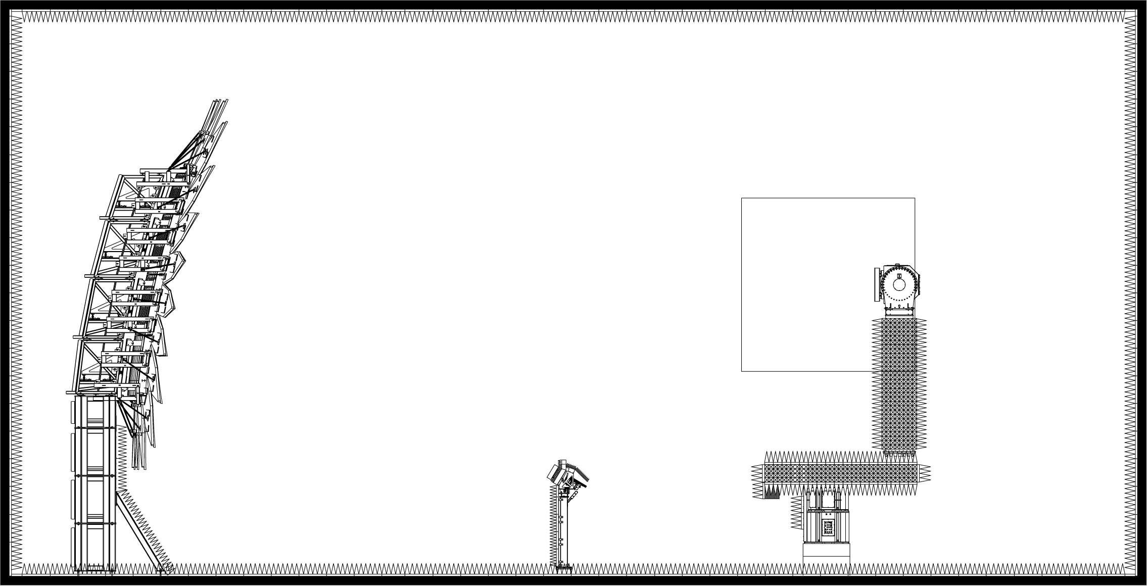
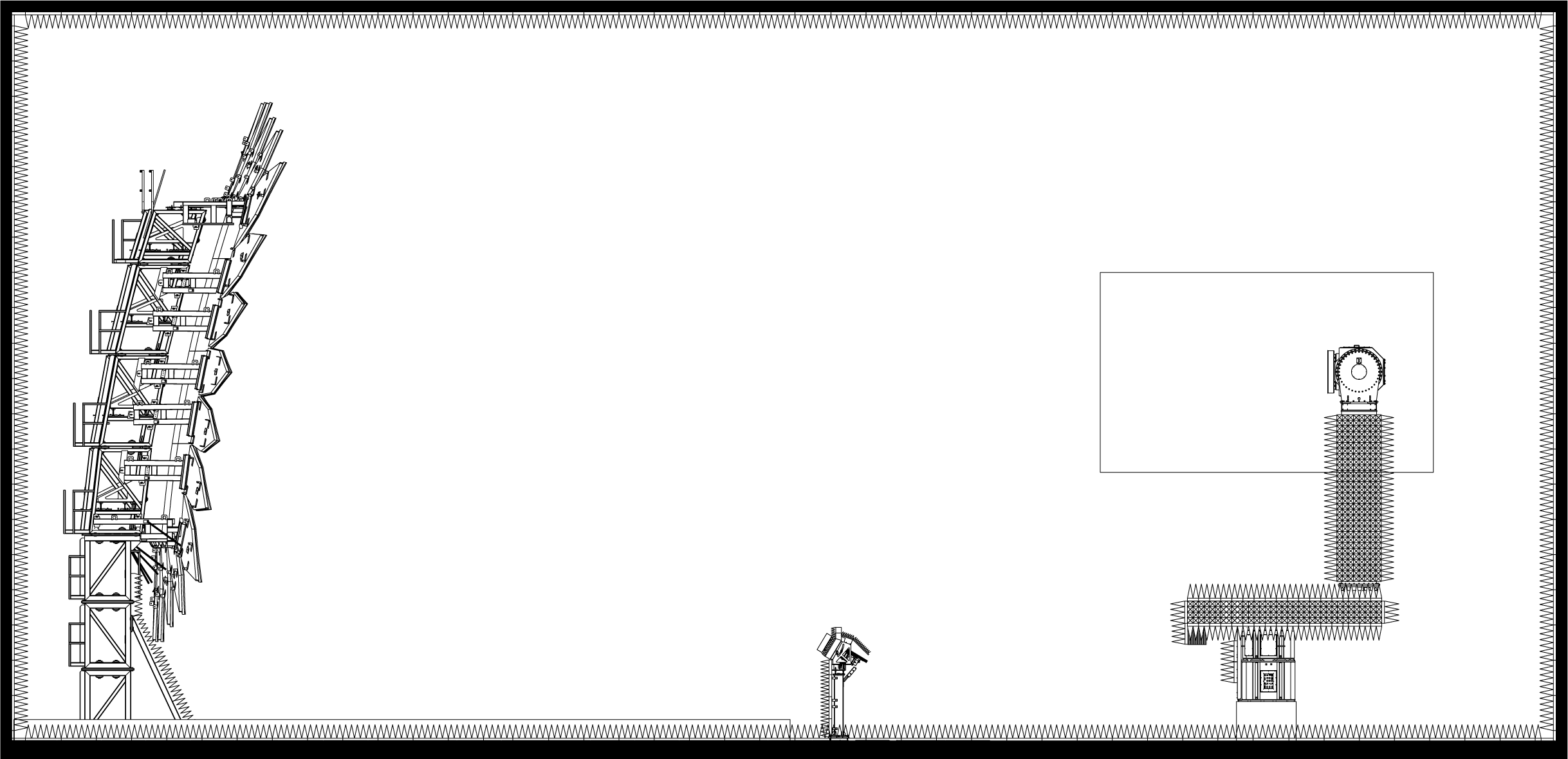
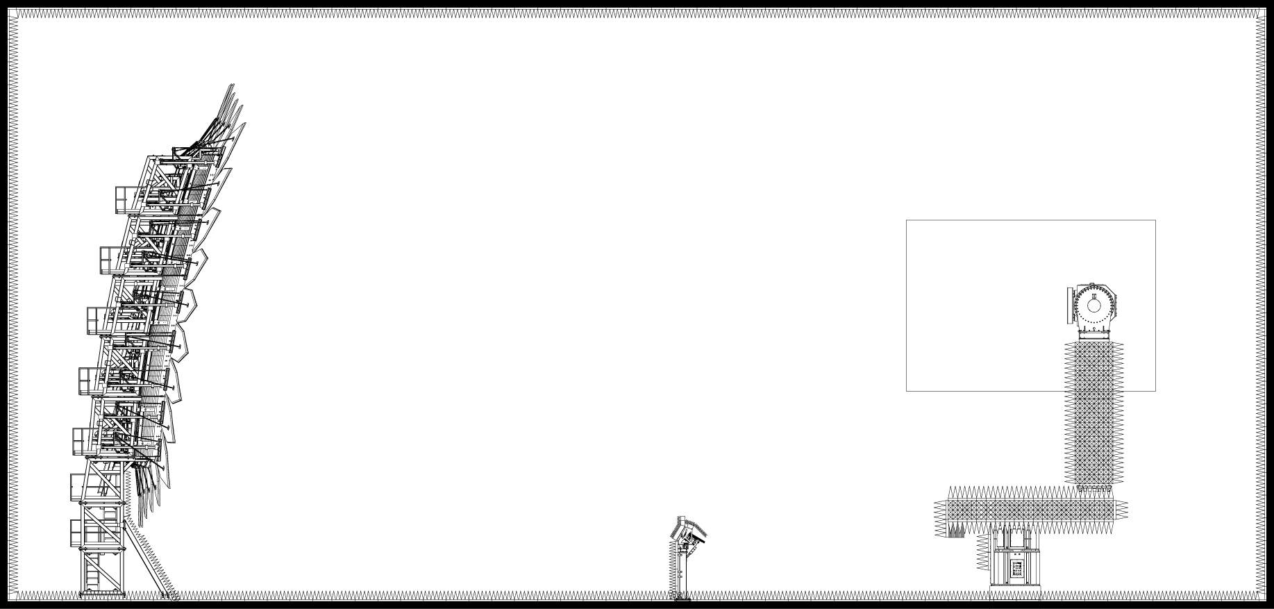
Compact Range System Construction
The major elements of the Large Compact Range Systems are highlighted below.

Anechoic Chamber with RF Absorber
With decades of combined experience, NSI-MI delivers turnkey anechoic environments that meet stringent quality standards and industry specifications. Our expert team supports every stage of the project—from CAD design and structural engineering to absorber layout and chamber integration—ensuring optimal quiet zone quality and measurement accuracy. NSI-MI’s engineers are highly skilled in RF antenna, radome, and RCS testing, consistently delivering reliable, high-performance results.


Compact Range Reflector
NSI-MI’s compact range reflector systems offer the full benefits of far-field testing in secure, indoor environments, dramatically reducing required test distances while maintaining accuracy. Available in a wide range of sizes and frequencies, these systems feature advanced serrated or rolled edge treatments to minimize diffraction and ensure clean wavefronts. Custom reflector designs are also available to meet specific electromagnetic requirements, making NSI-MI a trusted provider of high-performance testing solutions.
Learn MoreFeed Positioner
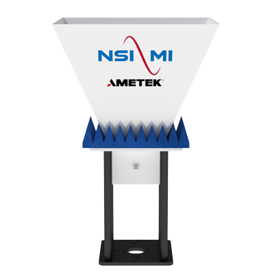
Designed for precision and adaptability, the Compact Range Feed Positioner delivers reliable support for single and dual-polarized feeds across discrete frequency bands. Engineered to ensure optimal feed alignment, it guarantees ideal reflector illumination—resulting in improved test accuracy and repeatability.
Precision Adjustability:
Effortlessly fine-tune both the distance and angle of the feed assembly to achieve ideal focus and alignment with the compact range reflector.
Automated Polarization Control:
Featuring a motorized polarization axis, the system enables smooth, automated rotation of the feed antenna—simplifying polarization adjustments and boosting operational efficiency.


AUT Positioner
NSI-MI’s AUT (Antenna Under Test) Positioner is purpose-built to securely support and precisely orient antennas within the quiet zone of the compact range—ensuring accurate and repeatable measurements. Its configurable multi-axis design allows for seamless adaptation to a wide range of testing scenarios. With a broad selection of standardized add-on options, the system offers exceptional flexibility to meet your specific application needs.
Learn MoreFeed Antennas
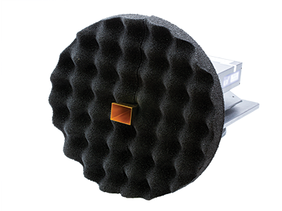
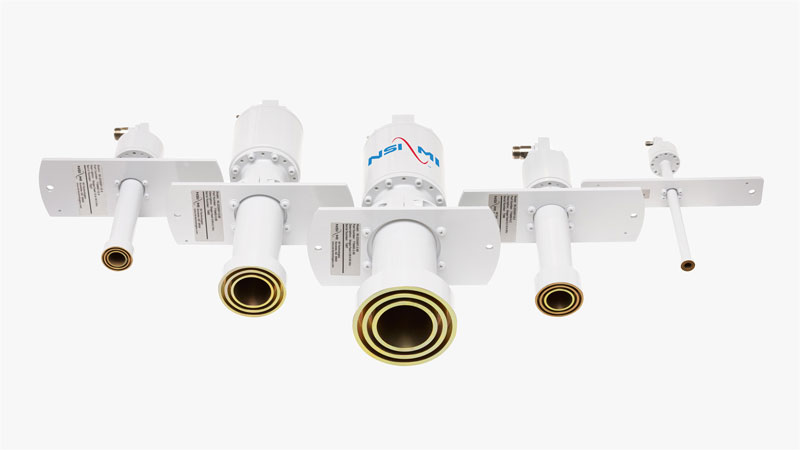
NSI-MI Technologies offers high-performance dual and linear polarized feed horns ideal for anechoic chamber applications, covering frequencies from 0.75 to 110 GHz. These feeds deliver broad, consistent beamwidths and low cross-polarization, ensuring optimal illumination for compact range reflectors. With customizable beamwidths and stable radiation patterns across the full waveguide band, they enhance measurement accuracy and chamber performance for antenna testing.
Linear Polarized Dual Polarized

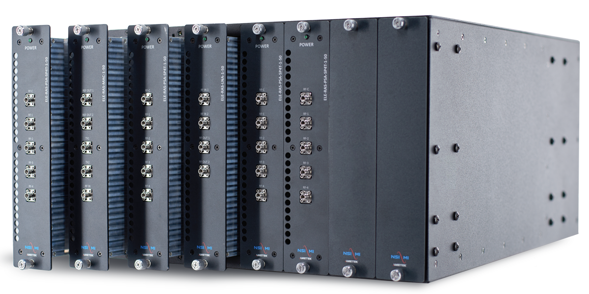
RF Subsystem with Rotary Joints and Cables
NSI-MI Technologies offers a fully integrated RF subsystem, enabling fast and accurate data acquisition to maximize range efficiency. The system includes scanner and range RF cables, rotary joints, RF components and devices, software drivers, and advanced data acquisition and plotting software. Designed for compatibility with both NSI-MI instrumentation—as well as many third-party systems—this subsystem ensures seamless operation and high-performance measurements in antenna testing environments.
Learn MoreData Acquisition and Analysis Workstation
NSI-MI’s Data Acquisition and Analysis Workstation creates and supports productive test environments with streamlined, fully automated systems for antenna, radome, and radar cross-section measurements. From setup to analysis and reporting, it delivers complete control and high-efficiency data handling for microwave and antenna testing. The workstation includes both hardware and software components, featuring NSI-MI’s A4 software for fast, reliable data acquisition, processing, and plotting—ensuring consistent performance across a wide range of measurement applications.
Learn More
Physical Parameters

-
Specifications
-
Absorber Kits
-
Applications
-
Available Add-Ons
| Parameters | CRS-CSC 3.7-1 |
CRS-ESC 2.4X3.7-0.5 |
CRS-CRC 5-0.35 |
CRS-CSC 6-0.5 |
CRS-ESC 5.5X9.1-0.5 |
CRS-ESC 7.3X10.7-0.5 |
| Quiet Zone Size |
ø3.7 x 3.7 m Circular Cylinder |
2.4 m (H) 3.7 m (W) 3.7 m (L) Elliptical Cylinder |
ø2 x 2 m (0.35–0.5 GHz) ø3 x 3 m (0.5–2 GHz) ø5 x 5 m (2–40 GHz) Circular Cylinder |
ø4 x 4 m (0.5–1 GHz) ø6 x 6 m (1–40 GHz) Circular Cylinder |
5.5 m (H) 9.1 m (W) 9.1 m (L) Elliptical Cylinder |
7.3 m (H) 10.7 m (W) 10.7 m (L) Elliptical Cylinder |
| ø12 x 12 ft Circular Cylinder |
8 ft (H) 12 ft (W) 12 ft (L) Elliptical Cylinder |
ø6.6 x 6.6 ft (0.35–0.5 GHz) ø9.8 x 9.8 ft (0.5–2 GHz) ø16.4 x 16.4 ft (2–40 GHz) Circular Cylinder |
ø13.1 x 13.1 ft (0.5–1 GHz) ø19.7 x 19.7 ft (1–40 GHz) Circular Cylinder |
18 ft (H) 30 ft (W) 30 ft (L) Elliptical Cylinder |
24 ft (H) 35 ft (W) 35 ft (L) Elliptical Cylinder |
|
| Frequency Range | 1–40 GHz |
0.5–40 GHz | 0.35–40 GHz | 0.5–40 GHz | 0.5–40 GHz | 0.5–40 GHz |
| Amplitude Taper* | ≤1.0 dB | ≤1.0 dB | ≤1.5 dB (0.35–0.5 GHz) ≤1.0 dB (1–40 GHz) |
≤2.0 dB (0.5–1 GHz) ≤1.0 dB (1–40 GHz) |
±1.75 dB (0.5–0.7 GHz) ±1.25 dB (0.7–1 GHz) ±1.0 dB (1–40 GHz) |
±1.0 dB |
| Amplitude Ripple* | ±0.5 dB | ±0.5 dB | ±1.0 dB (0.35–0.5 GHz) ±0.5 dB (1–40 GHz) |
±0.5 dB | ≤0.75 dB (0.5–1 GHz) ≤0.5 dB (1–40 GHz) |
≤0.5 dB |
| Phase Variation* | ±5° (1–18 GHz) ±10° (18–40 GHz) |
±5° (0.5–18 GHz) ±10° (18–40 GHz) |
±7° (0.35–1 GHz) ±5° (1–18 GHz) ±10° (18–40 GHz) |
±10° (0.5–2 GHz) ±5° (2–18 GHz) ±10° (18–40 GHz) |
±7° (0.5–7 GHz) ±6° (0.7–1 GHz) ±5° (1–18 GHz) ±10° (18–40 GHz) |
±5° (0.5–18 GHz) ±10° (18–40 GHz) |
| Cross Polarization (On-Axis) |
≤ -30 dB |
≤ -20 dB (0.5–1GHz) ≤ -30 dB (1–40 GHz) |
≤ -20 dB (0.35–1 GHz) ≤ -30 dB (1–40 GHz) |
≤ -25 dB (0.5–2 GHz) ≤ -30 dB (2–40 GHz) |
≤ -20 dB (0.5–1 GHz) ≤ -30 dB (1–40 GHz) |
≤ -25 dB |
| Load Capacity, Operation |
800 kg (1,764 lb) |
907 kg (2,000 lb) |
3,000 kg (6,614 lb) |
3,000 kg (6,614 lb) |
3,000 kg (6,614 lb) |
3,000 kg (6,614 lb) |
| Bending Moment, Operation |
5,423 Nm (4,000 ft-lb) |
5,423 Nm (4,000 ft-lb) |
67,791 Nm (50,000 ft-lb) |
67,791 Nm (50,000 ft-lb) |
67,791 Nm (50,000 ft-lb) |
67,791 Nm (50,000 ft-lb) |
| Feed Travel | ±200° / Continuous | |||||
| Roll Travel | ±200° / Continuous | |||||
| Upper Elevation Travel |
N/A | N/A | -5° to +95° | -5° to +95° | -5° to +95° | -5° to +95° |
| Offset Slide Travel | 1.1 m (3.6 ft) | 1.7 m (5.6 ft) | 1.8 m (5.9 ft) | 1.8 m (5.9 ft) | 1.8 m (5.9 ft) | 1.8 m (5.9 ft) |
| Azimuth Travel | ±200° Continuous |
|||||
| Feed Delivered Torque | 136 Nm (100 ft-lb) |
|||||
| Roll Delivered Torque | 678 Nm (500 ft-lb) |
678 Nm (500 ft-lb) |
13,558 Nm (10,000 ft-lb) |
13,558 Nm (10,000 ft-lb) |
13,558 Nm (10,000 ft-lb) |
13,558 Nm (10,000 ft-lb) |
| Upper Elevation Delivered Torque |
N/A | N/A | 50,000 Nm (67,791 ft-lb) |
50,000 Nm (67,791 ft-lb) |
50,000 Nm (67,791 ft-lb) |
50,000 Nm (67,791 ft-lb) |
| Azimuth Delivered Torque |
8,135 Nm (6,000 ft-lb) |
8,135 Nm (6,000 ft-lb) |
17,626 Nm (13,000 ft-lb) |
17,626 Nm (13,000 ft-lb) |
17,626 Nm (13,000 ft-lb) |
17,626 Nm (13,000 ft-lb) |
| Feed Speed | 48°/sec | |||||
| Roll Speed | 12°/sec | 12°/sec | 3°/sec | 3°/sec | 3°/sec | 3°/sec |
| Upper Elevation Speed |
N/A | N/A | 0.5°/sec | 0.5°/sec | 0.5°/sec | 0.5°/sec |
| Azimuth Speed | 2.4°/sec | 2.4°/sec | 3°/sec | 3°/sec | 3°/sec | 3°/sec |
| Feed Position Readout Accuracy |
±0.07 | |||||
| Roll Position Readout Accuracy |
±0.04° ±0.005° |
±0.04° ±0.005° |
±0.03° ±0.005° |
±0.03° ±0.005° |
±0.03° ±0.005° |
±0.03° ±0.005° |
| Upper Elevation Position Readout Accuracy |
N/A | N/A | ±0.04° ±0.005° |
±0.04° ±0.005° |
±0.04° ±0.005° |
±0.04° ±0.005° |
| Offset Slide Position Readout Accuracy |
±0.25 mm (±0.01 in.) Motorized | |||||
| Azimuth Position Readout Accuracy |
±0.04° ±0.005° |
±0.04° ±0.005° |
±0.02° ±0.005° |
±0.02° ±0.005° |
±0.02° ±0.005° |
±0.02° ±0.005° |
| Physical Parameters | CRS-CSC 3.7-1 |
CRS-ESC 2.4X3.7-0.5 |
CRS-CRC 5-0.35 |
CRS-CSC 6-0.5 |
CRS-ESC 5.5X9.1-0.5 |
CRS-ESC 7.3X10.7-0.5 |
| Recommended chamber size (Interior wall dimensions, H x W x L) |
10.5 x 11.5 x 22.5 m 34.5 x 37.7 x 73.8 ft |
13.7 x 14.6 x 27 m 45 x 48 x 89 ft |
17 x 17 x 34 m 56 x 56 x 112 ft |
20 x 23 x 40 m 66 x 76 x 131 ft |
20.4 x 23.8 x 56 m 67 x 78 x 185 ft |
25 x 29.3 x 62 m 82 x 96 x 204 ft |
| Absorber Size | 610 mm (24 in) |
1,219 mm (48 in) |
1.829 mm (72 in) |
1,219 mm (48 in) |
1,219 mm (48 in) |
1,219 mm (48 in) |
| Environmental Parameters | ||||||
| Operating conditions | Controlled indoor environment | |||||
| Operating temperature range, Survival temperature range |
18 to 24 °C (65 to 75 °F) 2 to 32 °C (36 to 90 °F) |
|||||
| Operating relative humidity, Survival relative humidity |
20 – 60% 20 – 60% |
|||||
| Supported Equipment, Software, and Accessories | ||||
| Position controller | ELE-PAC Precision Axis Controller |
|||
| Supported software | SW-A4 Advanced Antenna Acquisition and Analysis (A4) Remote control via SCPI command set (ELE-PAC & ELE-PMC only) |
|||
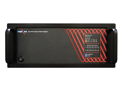
| RF receivers | ELE-VFA Vector Field Analyzer™ Select Keysight VNA models Select Rohde & Schwarz VNA models |
|||
| Frequency extension | Select Virginia Diodes Inc. (VDI) frequency extension modules | |||
| Feed antennas | ANT-LPF Linear Polarized Feeds ANT-DPF Dual Polarized Feeds Custom broadband options available for some applications |
|||
*Specifications apply to full quiet zone at a 95% statistical confidence level. Statistical confidence level varies based on the quality and design of chamber and thermal conditions.
System Absorber Kits
Absorber treatment, especially in the area surrounding the feed positioner, is crucial to maintaining ideal quiet zone performance across the operating frequency. The standard configuration includes polyurethane foam absorber, which supports RF power levels of ≤ 1 kW/m2 at full continuous wave (CW) power throughout most of the chamber. A high-power absorber solution is assembled using honeycomb absorber, which can support more than 10 kW/m2 at full CW power in the illumination region of the focused beam lens system. Should it be needed, NSI-MI can upgrade the critical areas to increase the power handling to 10 kW/m2 and beyond. Our experts in anechoic range design and electromagnetic analysis can help you determine which absorber kit is right for your application.

Foam Absorber
Standard option
≤ 1 kW/m2

Filter Foam Absorber
High-power option
≤ ~4 kW/m2

Honeycomb Absorber
Very high-power option
≤ ~10 kW/m2


Honeycomb Absorber with Forced Air Cooling - Extremely high-power option (air flow dependent)
- Antenna Radiation Pattern Measurement – Determines how antennas radiate energy in space.
- Wireless Device Testing – Tests mobile phones, IoT devices, Wi-Fi routers, etc.
- Radar Cross Section (RCS) Measurement – Assesses how objects reflect radar signals, used in stealth tech.
- Satellite and Aerospace Antenna Testing – Simulates space-like conditions for satellite systems.
- Automotive Radar and Sensor Testing – Tests radar systems in autonomous and assisted driving.
- Full range of Probes and Standard Gain Horns
- Additional software to enhance productivity
- AUT supports, stands and other accessories
- On-site installation, training and verification by NSI-MI experts
- Interface Kits to easily integrate a wide variety of common RF equipment, antennas and test devices
RF Options
- RF Frequency Options: 20, 40, 50 GHz
- RF Receiver Options: NSI-MI or Customer Supplied
Range Automation System Option
Automates common RF reconfiguration tasks to greatly improve range throughput and measurement accuracy.
Standard Gain Horn Antennas
Designed to support accurate and repeatable antenna gain calibration measurements.
Carousel Feed Positioner
mmWave RF Upgrade Options
- mmWave Band: 50–75 GHz module and Feed-SGH set
- mmWave Band: 60–90 GHz module and Feed-SGH set
- mmWave Band: 75–110 GHz module and Feed-SGH set
Compact Range Feed Options (Single/Dual-Polarized)
- Linear/Dual Polarized Feeds: 2.6–18
- Linear/Dual Polarized Feeds: 3.95–26
- Linear/Dual Polarized Feeds: 3.95–40
- Linear/Dual Polarized Feeds: 3.95–50
Software Upgrades
- Additional A4 Software License
- Professional Upgrade
- Enterprise Upgrade
- Ultimate Upgrade